Radio hacking is the practice of intercepting, analyzing, and sometimes generating radio signals to understand how wireless devices actually communicate. Every remote control, sensor, and wireless gadget in a typical household is quietly talking over the air, usually with no real protection against someone listening in or talking back. Compared to web or network security, RF is underexplored territory for most people getting into security research, mostly because it feels like it needs specialized, expensive equipment. But a Raspberry Pi, a cheap RTL-SDR dongle, and free software is already enough to get started. This post walks through setting that toolchain up from nothing, and getting a working transmit-and-decode loop running for three fundamental digital modulation types: ASK, FSK, and PSK.
Theory
The radio spectrum
The radio spectrum is the range of electromagnetic frequencies used for wireless communication, roughly from a few kHz up into the hundreds of GHz. Different slices of that spectrum are allocated for different purposes: broadcast FM radio, Wi-Fi, cellular networks, aviation, and a set of license-exempt bands set aside for short-range devices like garage remotes, weather stations, and similar low-power gear. These license-exempt bands are usually called ISM bands (Industrial, Scientific, and Medical), a designation that lets anyone transmit without applying for a license of their own, provided they stay inside a strict set of technical limits on power, duty cycle, and bandwidth, covered further down. Which slice a signal lives in isn't arbitrary. It's the result of decades of international coordination over who gets to use what, and it's the reason a large chunk of "getting started" in RF is actually regulatory, not technical.
E.R.P.
e.r.p. is the power an antenna actually radiates in its strongest direction, after accounting for the antenna's own gain. A transmitter putting out 10 mW into an antenna with 3 dB of gain radiates roughly 20 mW e.r.p. in that antenna's favored direction. Regulators cap e.r.p. rather than the transmitter's raw output power because e.r.p. reflects what's actually leaving the antenna, which is what determines how far a signal reaches and how much it can interfere with other devices sharing the band.
Duty cycle
Duty cycle is the fraction of time a transmitter is actually sending, expressed as a percentage of a fixed time window. A device limited to a 1% duty cycle gets 36 seconds of airtime per hour, a common limit for low-power ISM devices. This is what lets a large number of devices, garage remotes, key fobs, weather stations, share a narrow band without piling on top of each other constantly.
Bandwidth
Bandwidth is the width of the frequency range a signal occupies, expressed in Hz: the gap between its highest and lowest significant frequency component. It matters twice over. Regulators cap how wide a signal is allowed to be, and the choice of modulation decides how wide it ends up being. FSK, covered below, needs more bandwidth than ASK for exactly this reason: it has to fit two separate frequencies instead of one.
The carrier wave
A carrier wave is an oscillating electromagnetic signal that carries the data transmitted over it: s(t) = A · sin(2πft + φ). It has three properties: how tall the wave is (amplitude, A), how fast it oscillates (frequency, f), and where it sits within its own cycle at a given moment (phase, φ).
Each property can be changed over time (t) to carry information. The process of changing one or more of these properties is called modulation.
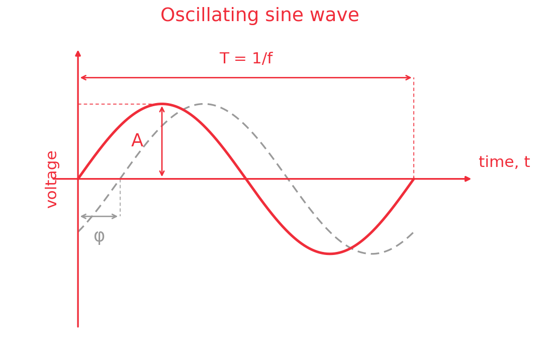
Image by National Institute of Standards and Technology (NIST) - Public Domain
Modulation
Modulation makes one or more of the three carrier properties vary over time, and it's that variation that encodes data. The reverse process, extracting that data back out of a received signal, is called demodulation. Each property gives its name to a modulation family:
ASK (Amplitude Shift Keying)
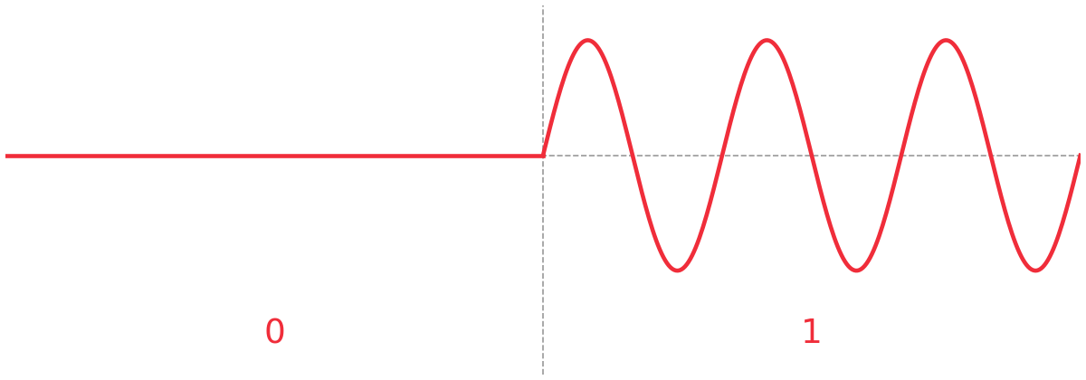
Amplitude switches between two or more discrete levels to represent bits. In the simplest and most common case, amplitude switches between zero and A_max, so the carrier turns fully off for a 0 and fully on for a 1. This binary case is called on-off keying (OOK).
FSK (Frequency Shift Keying)
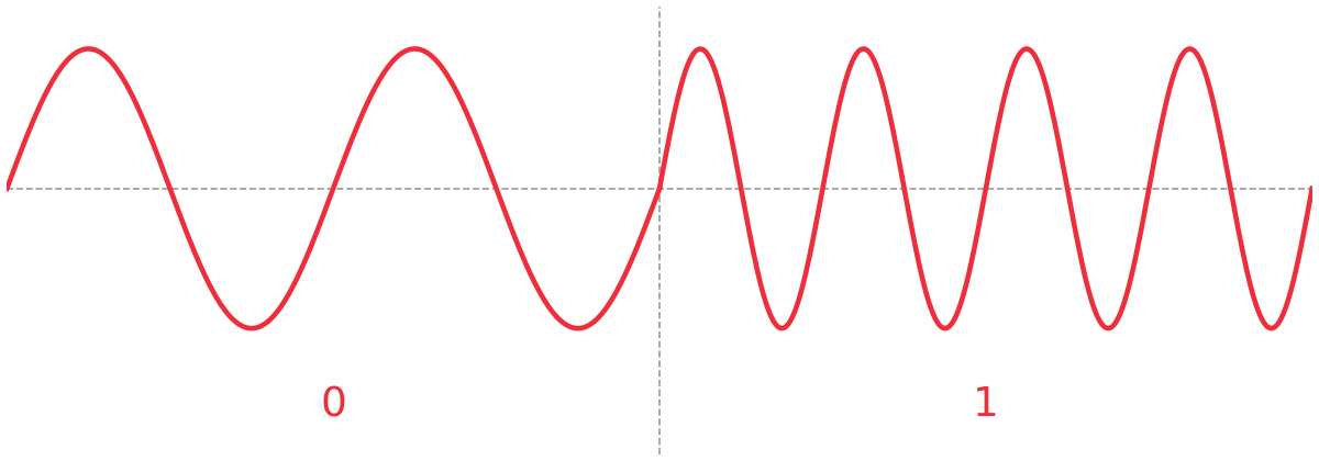
Frequency switches between two or more discrete frequencies to represent bits, for example 433.42 MHz for a 0 and 433.62 MHz for a 1. The offset from the carrier's center frequency to each of those shift frequencies is the frequency deviation, here 100 kHz, half the 200 kHz gap between the two tones. Because decoding depends on which frequency is present rather than the carrier's amplitude, FSK holds up better against the kind of amplitude noise that trips up ASK. The cost is bandwidth: the signal has to occupy enough spectrum to fit both frequencies.
PSK (Phase Shift Keying)
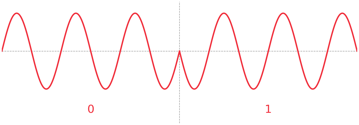
Phase switches between two or more discrete offsets to represent bits, for example 0° for a 1 and 180° for a 0, the simplest case, known as binary phase shift keying (BPSK). On a scope this shows up as a subtle jump in the wave at each symbol boundary: the amplitude and frequency of the wave never change, only where it sits in its cycle. Because decoding depends on timing rather than amplitude, PSK is the least sensitive of the three to amplitude noise, which is why it shows up in more demanding links like satellite and cellular. The trade-off lands on the receiver: recovering phase accurately means tracking a reference that transmitter and receiver both agree on, and even a correctly recovered reference can lock onto the wrong polarity, a 180° ambiguity that flips every decoded bit, covered later when demodulating a real capture.
Before we get started
DISCLAIMER: Before you try to replicate anything, it is important to check your local regulations!
Everything below is specific to Belgium, and it's exactly the part anyone replicating this needs to check for their own country before transmitting anything. The rules aren't the same everywhere, and getting them wrong turns a hobby project into a violation of telecom regulations.
Picking a frequency
Belgium follows the ETSI harmonized standard for short-range devices (EN 300 220), referenced through Decision 2006/771/EC and ERC/REC 70-03. BIPT, Belgium's telecom regulator, publishes the national implementation of this standard directly, in its national frequency plan. The relevant entry, Radio Interface Specification B01-18, covers non-specific short-range devices:
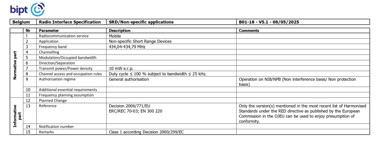
I chose this band because it's unlicensed and its duty cycle limit is 100%, meaning effectively no duty cycle restriction at all. This means I can transmit continuously, and I only have to worry about staying under a 25 kHz bandwidth and 10 mW e.r.p.
Everything that I will transmit targets 434.4 MHz, sitting near the middle of the 434.04-434.79 MHz slice, 360 kHz above the lower edge and 390 kHz below the upper edge before crossing into a neighboring allocation with different rules.
Staying under the power limit
Measuring e.r.p. is not possible with the tools I have available. So I leaned on hardware specs, some math, and whatever numbers other people online claim to have measured.
In the readme of the rpitx repository and the community around it, 10 mW is the number that keeps coming up, though it's not a measurement, and the community itself doesn't agree on it, with estimates elsewhere running closer to 1 mW and 100 mW depending on the frequency.
The GPIO pin runs at 3.3 V with a rated max of 16 mA, giving a theoretical ceiling of 52.8 mW. Wiring GPIO 4 to GND over a 330 ohm resistor gave me 2.88 V and 8.1 mA, or 23.33 mW, off real hardware. But that's a DC test at zero Hz, and rpitx transmits by toggling the pin at 434.4 MHz, not holding it high, so this tells me how hard the pin pushes, not what leaves the antenna.
With the lack of proper equipment I took a calculated bet and cut the antenna short. A resonant quarter-wave at 434.4MHz would be 17.25cm long, mine is 4.25cm long, roughly four times shorter. Antennas this short carry very low radiation resistance against the pin's 50 ohm source impedance, which is why cutting it short should work. That mismatch puts my best guess somewhere in the low single digit milliwatts, though I'm treating it as a reason to believe I'm under the limit, not proof of it.
Building the transmitter
With the legal and power questions settled, it was time to actually build the thing. rpitx turns a Raspberry Pi's GPIO pin into an RF transmitter directly, by manipulating the Pi's PLL and DMA timing, no separate transmitter chip needed. I connected the trimmed antenna to GPIO 4.
I cloned the repository on the Pi, then ran the project's own install script, which pulls in the build dependencies and compiles rpitx from source. That same script also disables the Pi's onboard audio, since it shares clock hardware that rpitx needs exclusive access to, which is why the last step is a reboot, to apply that change:
git clone https://github.com/F5OEO/rpitx
cd rpitx
./install.sh
sudo shutdown -r now
Before sending any data, I confirmed the full chain end to end, Pi, antenna, air, RTL-SDR, laptop, with a bare carrier:
sudo ./tune -f 434400000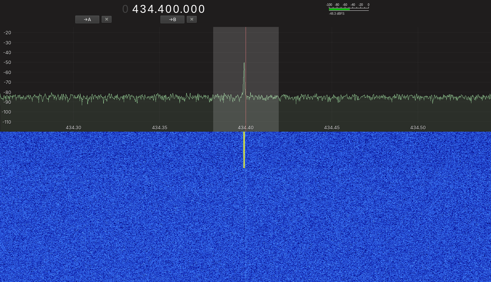
This produced a clean, single spike on both the spectrum and the waterfall, confirming the chain worked end to end before moving on to actual data. The transmitter sat right next to the receiver for every capture in this post, worth flagging up front since it means the signal levels on GQRX read stronger than the 10 mW e.r.p. limit alone would produce at any real distance.
With the carrier confirmed clean and where expected, I carried the same setup through for every signal in the rest of this post.
ASK: turning the carrier on and off
ASK was the first modulation I tested, encoding each bit as the carrier simply being on or off. The script below generates the actual IQ file sendiq transmits: for every bit it appends a block of samples at either full amplitude (1.0 + 0j) for a 1 or zero (0j) for a 0, one block per bit at the chosen bit rate. NumPy holds those samples as complex64 values, but sendiq reads plain interleaved float32 pairs, real, imaginary, real, imaginary, and so on, not a complex type, so the last few lines split every sample into its two components before writing them out as ask_test.iqf:
import numpy as np

bits = "10110010"
sample_rate = 125000
bit_duration = 0.001
samples_per_bit = int(sample_rate * bit_duration)

samples = []
for bit in bits:
    amplitude = 1.0 if bit == "1" else 0.0
    samples.extend([amplitude + 0j] * samples_per_bit)

iq_array = np.array(samples, dtype=np.complex64)
interleaved = np.empty(iq_array.size * 2, dtype=np.float32)
interleaved[0::2] = iq_array.real
interleaved[1::2] = iq_array.imag
interleaved.tofile("ask_test.iqf")
I transmitted that file with rpitx's sendiq binary, which streams raw IQ samples straight out through the GPIO pin: -s sets the sample rate to match what the script generated at, -f sets the 434.4 MHz center frequency, -t float tells it to expect the interleaved float32 format just written, -p 1.0 keeps the output at unity gain, and -l loops the file so there's a continuous signal to capture on the other end:
sudo ./sendiq -i ask_test.iqf -s 125000 -f 434400000 -t float -p 1.0 -l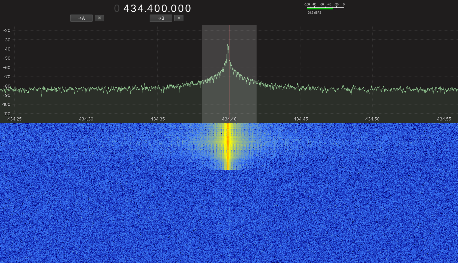
The peak is visible with a wide skirt spreading out from it, unlike the narrow single spike of the bare carrier test.
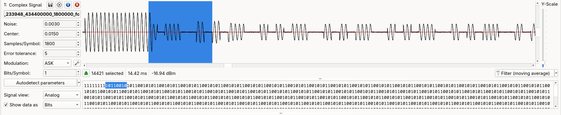
After filtering the moving average and setting the noise in the interpretation tab, URH automatically decoded the signal correctly. The bit sequence matched the transmitted 10110010 pattern exactly, repeating cleanly across the looped transmission.
FSK: shifting between two tones
FSK holds the carrier's amplitude constant and shifts its frequency instead, encoding each bit as one of two tones spaced symmetrically around the center frequency. The script below tracks phase continuously across bit boundaries rather than resetting it at every symbol: each bit picks a frequency offset, +deviation Hz for a 1 or -deviation Hz for a 0, and every sample within that bit advances a running phase by 2π · freq_offset / sample_rate before np.exp(1j * phase) turns it into the output sample. Tracking phase this way, instead of generating each bit's tone independently, keeps the waveform continuous across the boundary between bits, avoiding the sharp phase jumps a naive per-bit approach would leave behind. The same interleaving as ASK turns the result into fsk_test.iqf:
import numpy as np

bits = "10110010"
sample_rate = 125000
bit_duration = 0.001
samples_per_bit = int(sample_rate * bit_duration)
deviation = 5000  # Hz

samples = []
phase = 0.0
for bit in bits:
    freq_offset = deviation if bit == "1" else -deviation
    for _ in range(samples_per_bit):
        phase += 2 * np.pi * freq_offset / sample_rate
        samples.append(np.exp(1j * phase))

iq_array = np.array(samples, dtype=np.complex64)
interleaved = np.empty(iq_array.size * 2, dtype=np.float32)
interleaved[0::2] = iq_array.real
interleaved[1::2] = iq_array.imag
interleaved.tofile("fsk_test.iqf")
Transmitted with the same command as ASK, just pointed at the new file:
sudo ./sendiq -i fsk_test.iqf -s 125000 -f 434400000 -t float -p 1.0 -l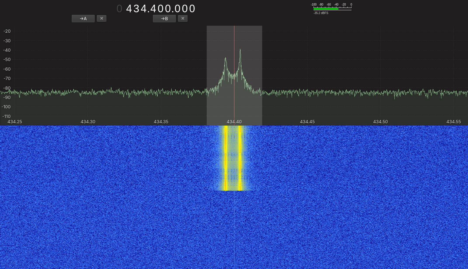
Here we can see two distinct peaks on GQRX instead of one, spaced apart by the designed ±5 kHz deviation between 434.395 and 434.405 MHz, staying inside the 25 kHz bandwidth budget for the chosen sub-band.
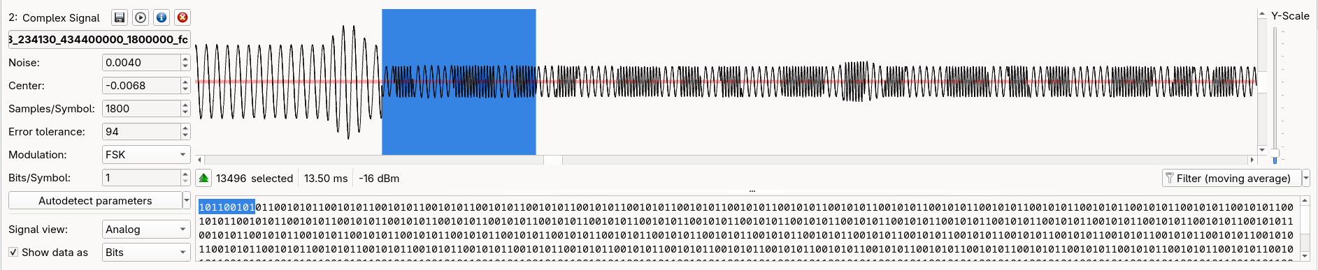
After filtering and setting noise again as with ASK I decoded the same 10110010 pattern, confirming the signal both by its shape on GQRX and by its content in URH.
PSK: a wave that stutters
PSK holds the carrier's amplitude and frequency constant and encodes data purely as a phase shift. The generator below is about as simple as modulation gets: each bit picks one of two fixed phases, 0° for a 1 and 180° for a 0, and every sample in that bit's block is np.exp(1j * phase), a unit-magnitude complex number sitting at that angle. The same interleaving as before turns it into psk_test.iqf:
import numpy as np

bits = "10110010"
sample_rate = 125000
bit_duration = 0.001
samples_per_bit = int(sample_rate * bit_duration)

samples = []
for bit in bits:
    phase = 0.0 if bit == "1" else np.pi
    samples.extend([np.exp(1j * phase)] * samples_per_bit)

iq_array = np.array(samples, dtype=np.complex64)
interleaved = np.empty(iq_array.size * 2, dtype=np.float32)
interleaved[0::2] = iq_array.real
interleaved[1::2] = iq_array.imag
interleaved.tofile("psk_test.iqf")
Same sendiq invocation once more, just pointed at the PSK file:
sudo ./sendiq -i psk_test.iqf -s 125000 -f 434400000 -t float -p 1.0 -l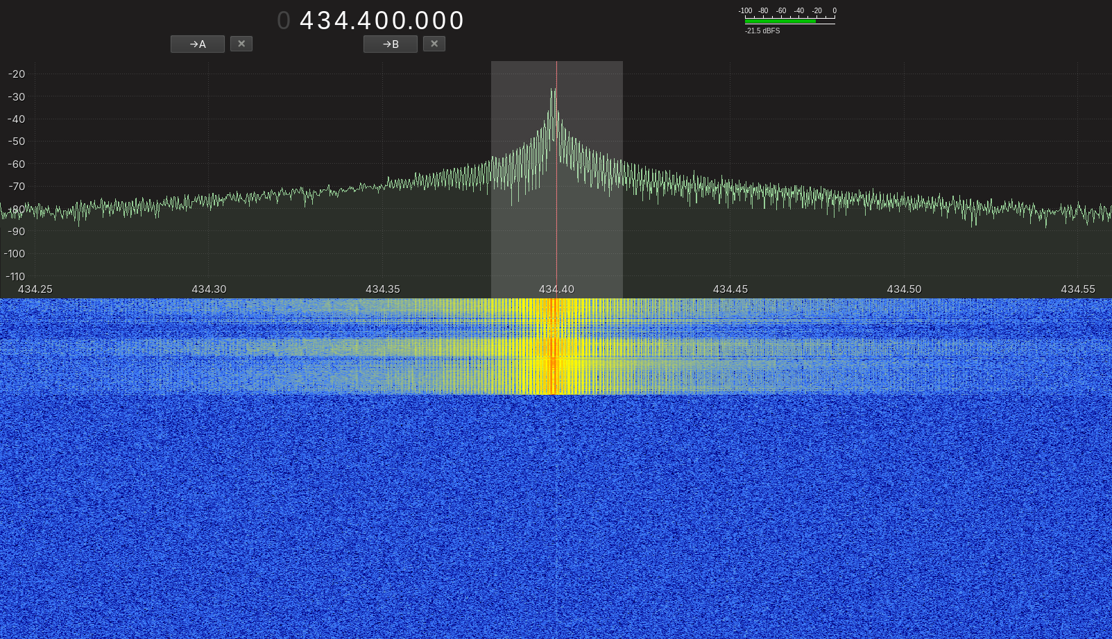
On GQRX, the PSK signal produced a single peak. That same close proximity between transmitter and receiver probably explains the noise around the signal here too.
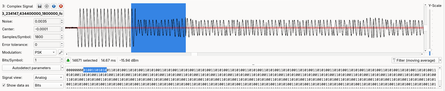
After putting the signal in URH, doing the same as before and setting the modulation type, I received an unexpected output. I got 01001101 instead of 10110010, which is the exact inverse.
This is a fundamental property of absolute-phase encoding. BPSK has no inherent reference point. Bit 1 was arbitrarily defined as 0° phase in the transmit script, but nothing in the signal itself communicates that convention to a receiver. URH settled on the opposite mapping, and both readings are equally valid interpretations of the same physical waveform, since correctness here only exists relative to a convention that has to be agreed upon separately, not something recoverable from the signal alone.
This is a well-documented limitation of plain BPSK, and it's exactly why real-world systems commonly use differential encoding (DBPSK) instead: encoding each bit as whether the phase changed from the previous symbol, rather than as an absolute phase value.
Since I already knew the correct bit sequence in advance, I resolved it on the receive side instead, by setting URH's decoding option to NRZ (non-return-to-zero) with inversion enabled in the analysis tab, which flips the bit-to-symbol mapping after demodulation to match. That's a receiver-side correction, and it only works because the correct answer was already known going in. A genuinely unknown captured signal would need the transmit-side fix, DBPSK, to be unambiguously decodable without prior knowledge.
Conclusion
Getting from a bare carrier to three working modulation types started with the regulatory groundwork: I picked 434.04-434.79 MHz as a license-free sub-band under Belgium's BIPT B01-18 specification and the underlying ETSI EN 300 220 standard, and stayed inside its 10 mW e.r.p. ceiling and 25 kHz bandwidth limit without any equipment capable of measuring e.r.p. directly. Cutting the antenna to roughly a quarter of its resonant length, against a power figure sourced from rpitx's own documentation and an independent hardware calculation, was my practical answer to that gap.
With the legal and power questions settled, I ran the same transmit-and-decode chain three times: ASK, FSK, and PSK, each generated from a known bit pattern, sent out from the Pi's GPIO pin, and confirmed independently through GQRX and URH.
PSK was the one that didn't come back clean. The phase ambiguity inherent to absolute-phase BPSK flipped every bit on the way through, and resolving it took two different fixes depending on whether the correct answer was already known going in: a receiver-side correction when it was, DBPSK's transmit-side fix when it isn't. That mismatch, and chasing it down, is the actual result of this post.